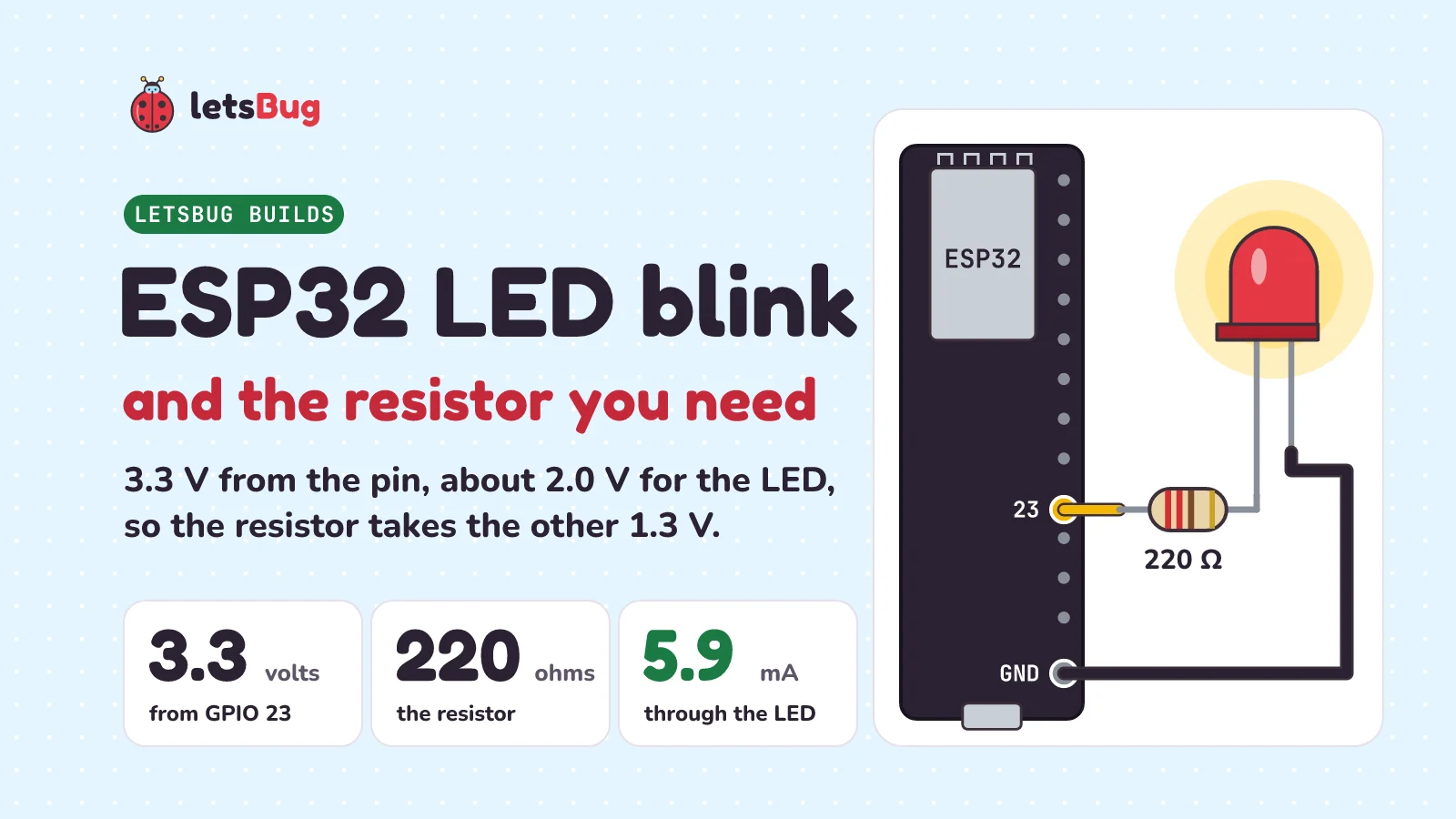
To blink an LED with an ESP32, run a wire from GPIO 23 to a 220 Ω resistor, the resistor to the LED's long leg, and the LED's short leg to GND. Then upload a ten-line Arduino sketch that switches the pin HIGH and LOW every 500 milliseconds. The resistor is the part beginners skip, and it's the one that matters. The pin gives 3.3 V, a red LED uses about 2.0 V, and nothing inside the LED stops the current from shooting up. The resistor takes the leftover 1.3 V and holds the current at about 5.9 mA. Let's wire it up, work out the resistor ourselves with Ohm's law, go through the code line by line, fix the usual upload error, and look up the real limits in Espressif's datasheet.
Key takeaways
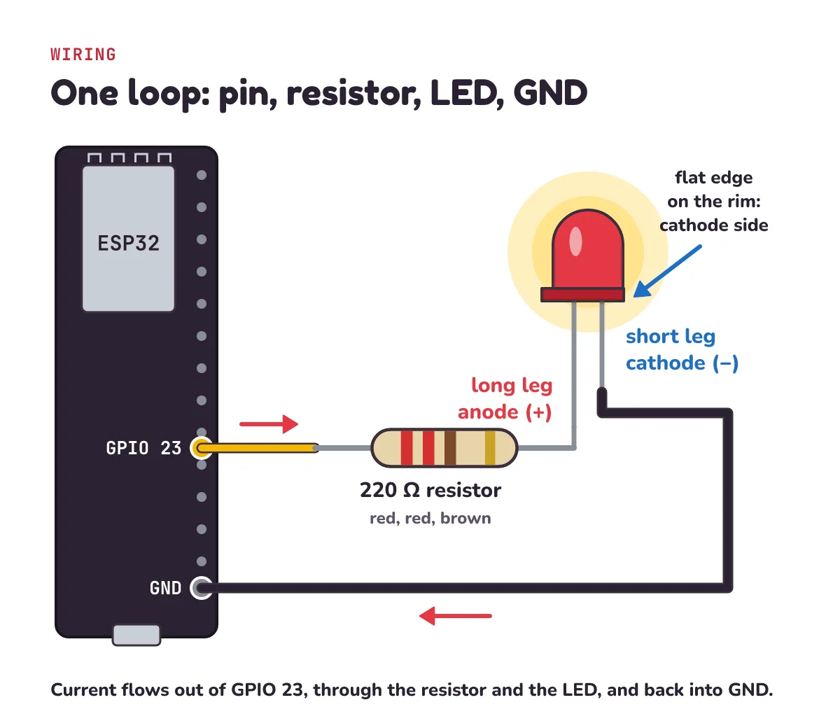
- The loop is GPIO 23 → resistor → LED long leg (anode, +) → LED short leg (cathode, −) → GND. An LED put in backwards just stays dark.
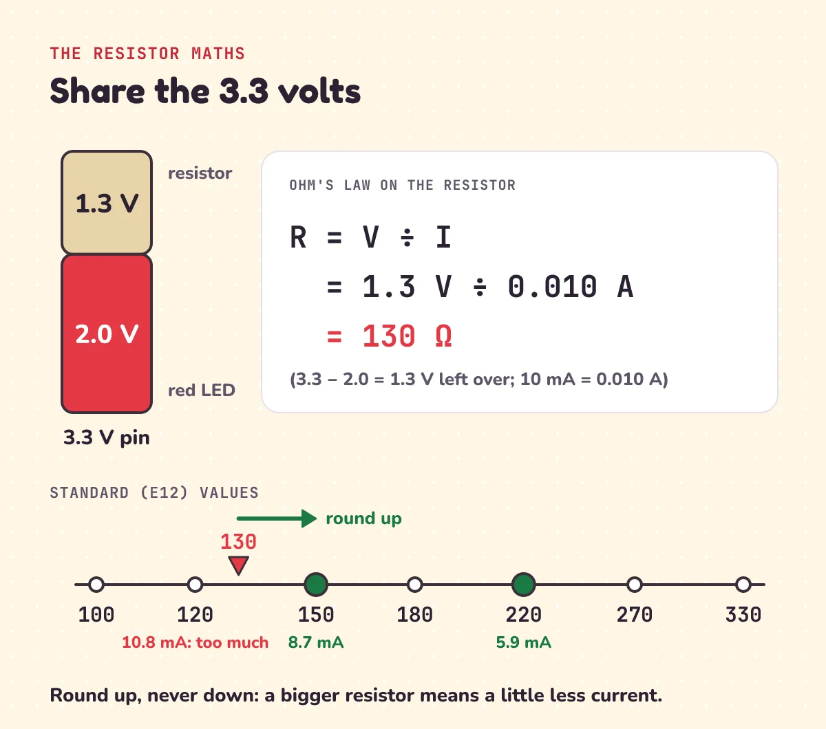
- Resistor = leftover voltage ÷ current. For a red LED at 10 mA: (3.3 − 2.0) ÷ 0.010 = 130 Ω. Round up to 150 Ω (about 8.7 mA), or use the 220 Ω from your kit (about 5.9 mA).
- The sketch is
pinMode(23, OUTPUT)once, thendigitalWriteHIGH, wait 500 ms, LOW, wait 500 ms, forever: one blink a second. - Keep outputs off the strapping pins (GPIO 0, 2, 5, 12, 15), the flash pins (GPIO 6 to 11), the input-only pins (GPIO 34 to 39) and TX/RX (GPIO 1 and 3).
- Never put 5 V on a GPIO pin: the datasheet's highest allowed HIGH input is 3.6 V. The "40 mA per pin" figure is a typical value at the pin's highest drive setting, never a target: keep each LED to about 10 mA.
This post goes with letsBug Builds, episode 1, the first in a series that builds up to a Wi-Fi weather station. Watch it first, or read on: everything in the video is here, plus a pin map, a table of resistor values, a mistakes table and a few challenges.
What you need
The ESP32 is a microcontroller made by Espressif: a small computer on one chip, with a processor, memory and pins that connect to the outside world. Most ESP32 chips have two cores at up to 240 MHz (there are single-core versions too), plus Wi-Fi (802.11 b/g/n) and Bluetooth 4.2 with Bluetooth LE. This post is for that original ESP32, on boards with an ESP32-WROOM-32 or WROVER module such as Espressif's DevKitC. The ESP32-S2, S3 and C3 are different chips with their own pin tables (on the S3, for example, the strapping pins are GPIO 0, 3, 45 and 46), so on those boards check your board's pinout first. For today, one detail matters most: its pins work at 3.3 V. A pin set HIGH sits at about 3.3 V; a pin set LOW sits at 0 V.
| Part | Notes |
|---|---|
| ESP32 development board | Any "DevKit" style board with an original ESP32 (WROOM-32 or WROVER module). We use the names on Espressif's ESP32-DevKitC V4; other boards print the same GPIO numbers but in different places. S2, S3 and C3 boards number their pins differently: check your board's pinout. |
| Breadboard | Any solderless breadboard. |
| Red LED | A plain 5 mm LED, the kind without a built-in resistor. |
| 220 Ω resistor | Four bands: red, red, brown, gold. Five-band (1%) resistors: red, red, black, black, brown. 150 Ω also works; the maths is below. |
| Jumper wires | Two male-to-male wires (female-to-male ones help on wide boards, see below). Yellow for the signal and black for ground make it easy to check. |
| USB cable | It must carry data. Some cables only charge, and with those the computer never sees the board. |
You also need the Arduino IDE on your computer. No programming experience is needed.
Wiring: GPIO 23, resistor, LED, GND
How a breadboard connects things
Under the plastic, each short row of five holes is joined by a metal clip, so anything plugged into the same row is connected. The long rails down the sides are joined along their length, so they're handy for ground. The gap down the middle separates the two halves, which is why the ESP32 board sits across it: each of its pins lands in its own row.
Which way round the LED goes
LED stands for light-emitting diode, and a diode lets current through in one direction only. The longer leg is the anode, the positive side. The shorter leg is the cathode, the negative side, and the rim of the LED has a flat edge on that side, which helps when the legs have been trimmed. Put it in backwards and, at 3.3 V, nothing breaks: it simply stays dark.
The four steps
Unplug the USB cable while you wire, and plug it back in only when the circuit is finished.
- Plug the ESP32 board across the middle gap of the breadboard.
- Find GPIO 23: on the DevKitC it's labelled IO23, the second pin on header J3, right next to a GND pin. Put one end of a jumper wire in a free hole in the same breadboard row as that pin, and the other end in an empty row away from the board.
- In that row, plug one leg of the resistor. Put its other leg in a new row, and plug the LED's long leg into that same row.
- Put the LED's short leg in the next row, and run a jumper wire from that row to a free hole in the same breadboard row as a GND pin.
Wide DevKit boards can cover almost the whole breadboard and leave one free hole per row, or none. If that happens, put the board across two breadboards side by side, or use a female-to-male jumper wire straight onto the pin.
Now current has a complete loop: out of the pin, through the resistor, through the LED and back to ground. The resistor can go on either side of the LED; all that matters is that it's in the loop.
Which ESP32 pins to avoid (and why GPIO 23)
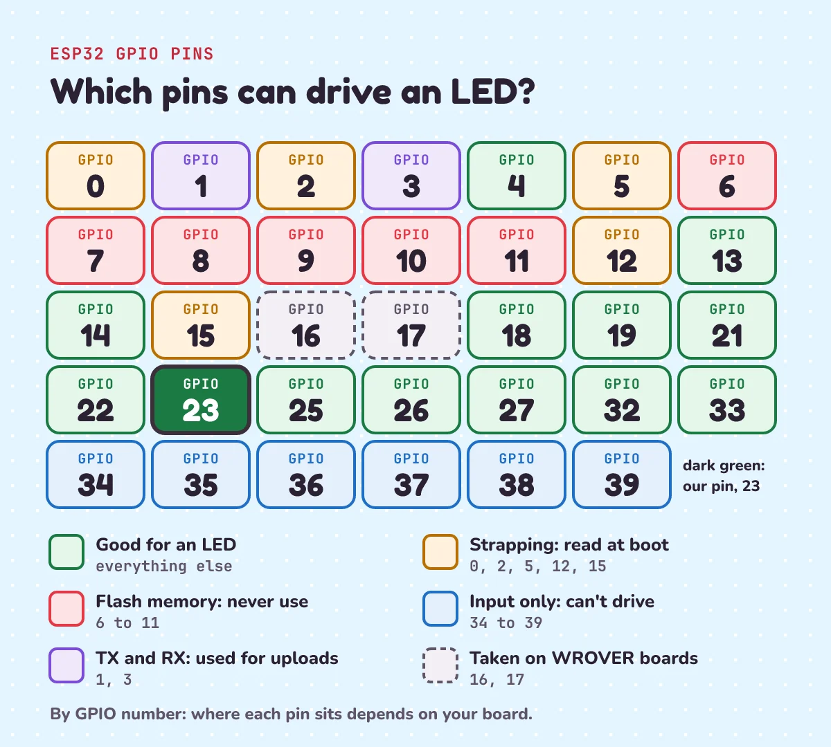
GPIO 23 is a plain input/output pin with no special job, and Espressif's pin table lists no restrictions for it. Several other pins do have a job:
- Strapping pins: GPIO 0, 2, 5, 12 and 15. The chip reads them at power-up or reset to decide how to start. GPIO 0 and GPIO 2 choose between running your program and waiting for a new one to be uploaded. Wire a circuit that pulls one of them the wrong way and the board may not start your sketch. After reset they work as normal pins, so the onboard LED that many third-party boards put on GPIO 2 is fine to blink, but your own circuits are safer elsewhere. (Espressif's own DevKitC has no GPIO 2 LED, only a 5 V power LED.)
- Flash pins: GPIO 6 to 11. They're wired to the flash memory that holds your program. Don't use them at all. On boards with an ESP32-WROVER module, GPIO 16 and 17 are taken by its extra memory too.
- Input-only pins: GPIO 34 to 39. They can read but can't drive an LED.
- GPIO 1 and 3 (TX and RX) carry the uploads from your computer, so keep them free.
Why the LED needs a resistor
An LED isn't like a light bulb. Below its threshold, about 2 V for a red LED, no current flows and it stays dark. Past that, the voltage across it stays nearly the same while the current shoots up: a small push in voltage brings a big jump in current. Nothing inside the LED holds the current back.
Connect it straight to a pin, and the only thing limiting the current is the pin's own output circuit. The LED pulls the pin down to about 2 V, well below the 2.64 V at which the datasheet specifies a pin's source current, so the pin is working outside its specified conditions and the LED gets far more than 10 mA. Too much current overheats an LED and can destroy it. The resistor is the speed bump. It takes up the leftover voltage and sets the current, because in a single loop the same current flows through every part.
The resistor maths: Ohm's law
Ohm's law says voltage equals current times resistance, V = I × R. Turn it round and resistance equals voltage divided by current, R = V ÷ I. The LED doesn't follow Ohm's law, but the resistor does, so we use it on the resistor's share of the voltage:
R = (supply voltage − LED voltage) ÷ current
- The pin gives 3.3 V. A red LED uses about 2.0 V (red LEDs run from about 1.63 to 2.03 V). That leaves 3.3 − 2.0 = 1.3 V for the resistor.
- For a bright LED that's well within its limits, aim for 10 mA (the typical 5 mm LED in SparkFun's guide is rated for 20 mA or less). Milli means a thousandth, so that's 0.010 A.
- R = 1.3 V ÷ 0.010 A = 130 Ω.
- Resistors come in standard values. The common E12 series goes 100, 120, 150, 180, 220, 270, 330 Ω and so on, with no 130. Round up, never down: a bigger resistor means a little less current, which is safe. The next value up is 150 Ω.
- Or just use 220 Ω, a common kit value (SparkFun suggests 330 Ω as a safe default for most LEDs). The current is then 1.3 V ÷ 220 Ω = 0.0059 A, about 5.9 mA. Still clearly bright, and gentle on everything.
Here's the same calculation for a few resistors you might have, with the red LED on a 3.3 V pin:
| Resistor | Current | Verdict |
|---|---|---|
| 120 Ω | 10.8 mA | Over our 10 mA target: this is why we round up |
| 150 Ω | 8.7 mA | Bright; the next value up from 130 Ω |
| 220 Ω | 5.9 mA | The kit value: bright enough, very safe |
| 330 Ω | 3.9 mA | Dimmer, still clearly on |
| 1,000 Ω | 1.3 mA | Dim, but fine as an indicator |
These are close, not exact. Real LEDs vary, and a pin's voltage can sag under load: the datasheet only promises at least 0.8 × 3.3 = 2.64 V at full drive. If it matters, measure it. With a multimeter, measure the voltage across the resistor and divide it by the resistance: that's your real current.
The video's pause-and-try question was a blue LED. It uses about 3.0 V, so at 5 mA: (3.3 − 3.0) ÷ 0.005 = 60 Ω, and the next E12 value up is 68 Ω. With only 0.3 V to spare, though, a small difference in the LED changes the current a lot. Blue LEDs range from about 2.48 to 3.7 V, so some barely light on 3.3 V at all.
The ESP32 blink code (Arduino sketch)
First, teach the Arduino IDE about the ESP32 (you only do this once):
- Open File > Preferences and paste this into Additional boards manager URLs:
https://espressif.github.io/arduino-esp32/package_esp32_index.json - Open Tools > Board > Boards Manager, search for esp32 and install the esp32 package from Espressif.
Then here's the whole sketch:
const int LED_PIN = 23;

void setup() {
  pinMode(LED_PIN, OUTPUT);
}

void loop() {
  digitalWrite(LED_PIN, HIGH);
  delay(500);
  digitalWrite(LED_PIN, LOW);
  delay(500);
}
Line by line:
const int LED_PIN = 23;gives the pin a name. If you move the LED to another pin, this is the only line to change.setup()runs once, when the board starts.pinMode(LED_PIN, OUTPUT)makes GPIO 23 an output, so the code can drive it.loop()runs again and again, forever.digitalWrite(LED_PIN, HIGH)sets the pin to 3.3 V, and the LED lights.delay(500)waits 500 milliseconds, half a second.digitalWrite(LED_PIN, LOW)sets the pin to 0 V, the LED goes dark, and anotherdelay(500)waits.
On for 500 ms plus off for 500 ms makes one blink every second. One thing to know about delay(): while it waits, your sketch does nothing else. That's fine for a blink. Later in the series, when the ESP32 also has to read a button, we'll need a better way.
Uploading (and the BOOT button)
- Plug in the board. In Tools > Board, choose your board; ESP32 Dev Module works for most DevKit-style boards.
- In Tools > Port, choose the port that appeared when you plugged in (for example COM5 on Windows, /dev/ttyUSB0 on Linux, or /dev/cu.usbserial-… on macOS).
- Press Upload.
If the upload stops with Failed to connect to ESP32: Timed out waiting for packet header, the board didn't go into its upload mode (Espressif calls it download mode). Press Upload again, and hold the BOOT button while the IDE tries to connect. Let go once it starts writing. The BOOT button is wired to GPIO 0, and holding GPIO 0 low while the chip resets is exactly the strapping-pin setting for "wait for a new program". If the sketch doesn't start by itself afterwards, press EN, the reset button. Your LED blinks.
Common mistakes
| What you see | Likely cause | Fix |
|---|---|---|
| LED never lights | LED in backwards | Turn it round: long leg towards the resistor and the pin |
| LED never lights | Resistor and LED leg in different rows, or the GND wire on the wrong row | Trace the loop hole by hole: pin, resistor, LED, GND |
| LED never lights | No pinMode(LED_PIN, OUTPUT) in setup() | Add it. In Espressif's ESP32 core, digitalWrite() on a pin that was never set up does nothing except log an error, which you only see with Tools > Core Debug Level set to Error or higher (it starts at None) |
| Board not in Tools > Port | Charge-only USB cable | Try another cable you know carries data, and plug straight into the computer |
| Board still not in Tools > Port, even with a data cable | The driver for the board's USB-to-serial chip is missing | Read the name on the small chip near the USB socket and install its driver: Espressif's own boards mostly use a CP210x (or FTDI); other boards may use a different chip, such as the CH340 |
Failed to connect to ESP32 | Board didn't enter upload mode | Hold BOOT while the upload starts; check nothing is wired to TX or RX |
| Uploads, but nothing happens | The board is still in upload (download) mode | Press EN (reset) |
| Ground rail doesn't connect | Some long breadboards split their rails in the middle | Use a GND row next to the LED, or bridge the two halves with a wire |
| "It worked fine without a resistor" | No current limit except the pin's output circuit | Put the resistor back. Working today doesn't mean it lasts |
Safety limits from the datasheet
These are the numbers worth knowing, all from Espressif's ESP32 datasheet:
- Never connect 5 V to a GPIO pin. Two tables in the datasheet set the limit. In Table 5-3 (DC characteristics), the highest allowed HIGH input on a pin is VDD + 0.3 = 3.3 + 0.3 = 3.6 V. In Table 5-1, the absolute maximum voltage on the supply pins is also 3.6 V, and Espressif warns that going past absolute maximum ratings "may cause permanent damage to the device". The 5V pin on your board is for powering things, never for a GPIO.
- About 40 mA per pin is never a target. Drive strength is how hard a pin can push current out, and source current is the current it pushes out when HIGH. The datasheet lists a typical source current of 40 mA, measured with the drive strength at its maximum setting: it's what a pin can push at its highest setting, not a working figure. The default drive strength is about 20 mA. The more pins source current at once, the lower the per-pin figure gets (towards about 29 mA). And 1,200 mA for all the pins together is an absolute maximum, a never-exceed number, not a budget. Keep each LED to about 10 mA; ours takes 5.9 mA.
- Never drive a motor straight from a pin. A pin is a signal, not a power supply. Put a transistor or a motor driver board between them. We'll get there in the series.
1) A green LED drops about 2.2 V on a 3.3 V ESP32 pin (that's the older yellow-green kind; bright modern green LEDs can need about 3 V, so check yours). What resistor gives 10 mA, and which standard value would you use?
2) You only have a 330 Ω resistor and a red LED (2.0 V). What current flows?
3) Add a second on-off pair and change the delays to make a heartbeat: two quick flashes, then a pause, still once a second.
Show the answers
1) (3.3 − 2.2) ÷ 0.010 = 110 Ω. That isn't a standard value, so round up to 120 Ω, which gives about 9.2 mA.
2) 1.3 V ÷ 330 Ω = 0.0039 A, about 3.9 mA: dimmer, but clearly on.
3) On 100, off 100, on 100, off 700. That's 1,000 ms in total, so the pattern repeats once a second:
const int LED_PIN = 23;

void setup() {
  pinMode(LED_PIN, OUTPUT);
}

void loop() {
  digitalWrite(LED_PIN, HIGH);
  delay(100);
  digitalWrite(LED_PIN, LOW);
  delay(100);
  digitalWrite(LED_PIN, HIGH);
  delay(100);
  digitalWrite(LED_PIN, LOW);
  delay(700);
}
Want a second LED? Give it its own resistor on another pin marked green (safe) on the pin map, such as GPIO 22, and set it HIGH whenever the first one is LOW.
Questions people ask
What resistor should I use for an LED on an ESP32?
220 Ω is a safe default for a red LED on a 3.3 V pin: about 5.9 mA. To work it out yourself, divide the leftover voltage by the current you want: (3.3 − 2.0) ÷ 0.010 = 130 Ω for 10 mA, rounded up to 150 Ω. Always round up.
Can I connect an LED to an ESP32 without a resistor?
It may light, but it's a bad habit: it risks the LED and runs the pin outside its specified conditions. Past its forward voltage an LED lets the current climb steeply, so the only limit left is the pin's own output circuit. Use a resistor every time, unless your LED has one built in.
Which ESP32 pin is the built-in LED?
On many third-party DevKit-style boards it's GPIO 2, but not on all. Espressif's own ESP32-DevKitC V4 has no user LED, only a 5 V power LED. Check your board's pinout. If it has one on GPIO 2, change LED_PIN to 2 to blink it.
Which ESP32 pins are safe for an LED?
Good choices are GPIO 4, 13, 14, 18, 19, 21, 22, 23, 25, 26, 27, 32 and 33 (plus 16 and 17 on WROOM boards). Avoid the strapping pins (0, 2, 5, 12, 15), the flash pins (6 to 11), TX and RX (1 and 3) and the input-only pins (34 to 39). GPIO 16 and 17 are fine on WROOM boards but taken on WROVER boards.
Why does my ESP32 say "Failed to connect" when uploading?
It didn't enter upload mode. Hold the BOOT button while the upload starts, then let go. Also try a USB cable that carries data, and make sure nothing is connected to TX or RX.
Is the ESP32 5 V tolerant?
No. Its pins work at 3.3 V, and the datasheet's limit is 3.6 V. Never connect 5 V to a GPIO. To read a 5 V signal, use a level shifter (a small board that converts between 5 V and 3.3 V signals) or a voltage divider.
Keep going
- Watch the full lesson, ESP32 LED Blink: First Project for Beginners, or the Short, why your LED needs a resistor. More in the letsBug Builds series on YouTube.
- When you press Upload, your sketch is compiled into machine code first. Here's that journey for a program on a computer: what happens when you run Hello World.
- The ESP32's Wi-Fi is where this series is heading. Here's what happens on the network side: how the internet works, step by step.
Sources
- Espressif: ESP32 Series Datasheet, v5.3 (cores, Wi-Fi and Bluetooth; Table 5-1 absolute maximum ratings; Table 5-3 DC characteristics; drive strength; boot mode strapping pins)
- Espressif: ESP-IDF GPIO reference for ESP32 (strapping, flash, input-only and TX/RX pins)
- Espressif: ESP32-DevKitC V4 user guide (header pins, BOOT and EN buttons, power LED, GPIO 16 and 17 on WROVER)
- Espressif: Installing the Arduino-ESP32 core (the Boards Manager URL)
- Espressif: Arduino-ESP32 troubleshooting (the "Failed to connect" error, the BOOT button, charge-only cables)
- Espressif: Establish Serial Connection with ESP32 (USB-to-serial drivers, port names) and the ESP32-S3 GPIO reference (its strapping pins)
- Arduino: digitalWrite() and delay() reference
- Espressif: arduino-esp32 source, esp32-hal-gpio.c (what
digitalWrite()does on a pin that isn't an output), esp32-hal-log.h and boards.txt (when that error is printed; the Core Debug Level menu) - SparkFun: Light-Emitting Diodes, Polarity, How to Use a Breadboard and How to Install CH340 Drivers
- Wikipedia: LED circuit, Light-emitting diode (forward voltage by colour), Ohm's law, E series of preferred numbers and Electronic color code
Every number in this post was recalculated in Python before publishing. Both sketches were checked line by line and their timing stepped through, but not compiled here: there's no Arduino toolchain on the machine that checked them.